 2:30
2:30
2024-02-24 08:51

 1:53
1:53

 1:53
1:53
2023-12-10 18:06

 2:36
2:36

 2:36
2:36
2025-02-28 06:32

 4:44
4:44

 4:44
4:44
2025-03-06 04:47

 4:31
4:31

 4:31
4:31
2024-04-05 18:15
 5:17
5:17

 5:17
5:17
2024-01-30 18:59

 27:39
27:39

 27:39
27:39
2024-09-27 17:25

 8:17
8:17

 8:17
8:17
2024-10-27 20:23

 26:46
26:46

 26:46
26:46
2024-11-08 19:55

 2:55
2:55

 2:55
2:55
2025-09-04 17:15
 1:11
1:11

 1:11
1:11
2025-02-27 10:07

 5:21
5:21

 5:21
5:21
2023-09-06 11:57

 11:55
11:55

 11:55
11:55
2023-09-08 15:53
 11:25
11:25

 11:25
11:25
2023-09-07 17:20

 1:28:12

 1:28:12
2023-03-31 11:15
![Buran Control System Система управления Бурана 1_4]() 15:00
15:00
 15:00
15:00
2021-09-04 23:50

 2:15
2:15

 2:15
2:15
2025-02-08 13:37
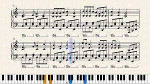
 2:11
2:11
![Рейсан Магомедкеримов, Ренат Омаров - Бла-та-та (Премьера клипа 2025)]() 2:26
2:26
![Фаррух Хамраев - Отажоним булсайди (Премьера клипа 2025)]() 3:08
3:08
![Светлана Ларионова - Осень отстой (Премьера клипа 2025)]() 3:30
3:30
![INSTASAMKA - BOSS (Премьера клипа 2025)]() 3:41
3:41
![KhaliF - Где бы не был я (Премьера клипа 2025)]() 2:53
2:53
![Сергей Одинцов - Девочка любимая (Премьера клипа 2025)]() 3:56
3:56
![Любовь Попова - Прощай (Премьера клипа 2025)]() 3:44
3:44
![Мария Зайцева - Жаль моя (Премьера клипа 2025)]() 4:25
4:25
![Zhamil Turan - Капали (Премьера клипа 2025)]() 3:08
3:08
![ARTIX - Ай, джана-джана (Премьера клипа 2025)]() 2:24
2:24
![MEDNA - Алё (Премьера клипа 2025)]() 2:28
2:28
![Magas - Без тебя (Премьера клипа 2025)]() 2:28
2:28
![Аля Вайш - По кругу (Премьера клипа 2025)]() 2:37
2:37
![Зара - Танго о двух влюбленных кораблях (Премьера клипа 2025)]() 3:10
3:10
![Игорь Крутой - Зонтик (Премьера клипа 2025)]() 4:00
4:00
![ARTEE - Лети (Премьера клипа 2025)]() 3:13
3:13
![Гор Мартиросян - 101 роза (Премьера клипа 2025)]() 4:26
4:26
![Бьянка - Бренд (Премьера клипа 2025)]() 2:29
2:29
![Зара - Я несла свою беду (Премьера клипа 2025)]() 3:36
3:36
![Жасурбек Мирзажонов - Суймаганга суйкалдим (Премьера клипа 2025)]() 5:45
5:45
![F1 (2025)]() 2:35:53
2:35:53
![Сумерки | Twilight (2008)]() 2:01:55
2:01:55
![Чумовая пятница 2 | Freakier Friday (2025)]() 1:50:38
1:50:38
![Пойман с поличным | Caught Stealing (2025)]() 1:46:45
1:46:45
![Лучшее Рождество! | Nativity! (2009)]() 1:46:00
1:46:00
![Эффект бабочки | The Butterfly Effect (2003)]() 1:53:35
1:53:35
![Голос любви | Aline (2020)]() 2:05:43
2:05:43
![Любимец женщин | Roger Dodger (2002)]() 1:41:29
1:41:29
![Школьный автобус | The Lost Bus (2025)]() 2:09:55
2:09:55
![Государственный гимн | Americana (2025)]() 1:47:31
1:47:31
![Лос-Анджелес в огне | Kings (2017)]() 1:29:27
1:29:27
![Стив | Steve (2025)]() 1:33:34
1:33:34
![Одноклассницы | St. Trinian's (2007)]() 1:36:32
1:36:32
![Свинтусы | The Twits (2025)]() 1:42:50
1:42:50
![Храброе сердце | Braveheart (1995)]() 2:57:46
2:57:46
![Мужчина у меня в подвале | The Man in My Basement (2025)]() 1:54:48
1:54:48
![Когда ты закончишь спасать мир | When You Finish Saving the World (2022)]() 1:27:40
1:27:40
![Сверху вниз | Highest 2 Lowest (2025)]() 2:13:21
2:13:21
![Плохие парни 2 | The Bad Guys 2 (2025)]() 1:43:51
1:43:51
![Элис, дорогая | Alice, Darling (2022)]() 1:29:30
1:29:30
![Супер Дино]() 12:41
12:41
![Артур и дети круглого стола]() 11:22
11:22
![МиниФорс]() 0:00
0:00
![Сборники «Ну, погоди!»]() 1:10:01
1:10:01
![Приключения Тайо]() 12:50
12:50
![Сборники «Оранжевая корова»]() 1:05:15
1:05:15
![Зебра в клеточку]() 6:30
6:30
![Отряд А. Игрушки-спасатели]() 13:06
13:06
![Паровозик Титипо]() 13:42
13:42
![Команда Дино Сезон 2]() 12:31
12:31
![Оранжевая корова]() 6:30
6:30
![Новогодние мультики – Союзмультфильм]() 7:04
7:04
![Рэй и пожарный патруль Сезон 1]() 13:27
13:27
![Последний книжный магазин]() 11:20
11:20
![Поймай Тинипин! Королевство эмоций]() 12:24
12:24
![Пиратская школа]() 11:06
11:06
![Корги по имени Моко. Домашние животные]() 1:13
1:13
![Монсики]() 6:30
6:30
![Школьный автобус Гордон]() 12:34
12:34
![Люк - путешественник во времени]() 1:19:50
1:19:50

 2:11
2:11Скачать видео
| 256x144 | ||
| 426x240 | ||
| 640x360 | ||
| 854x480 | ||
| 1280x720 | ||
| 1920x1080 |
 2:26
2:26
2025-10-22 14:10
 3:08
3:08
2025-10-18 10:28
 3:30
3:30
2025-10-24 11:42
 3:41
3:41
2025-10-23 13:04
 2:53
2:53
2025-10-28 12:16
 3:56
3:56
2025-10-28 11:02
 3:44
3:44
2025-10-21 09:25
 4:25
4:25
2025-10-17 11:28
 3:08
3:08
2025-10-22 14:26
 2:24
2:24
2025-10-28 12:09
 2:28
2:28
2025-10-21 09:22
 2:28
2:28
2025-10-17 12:00
 2:37
2:37
2025-10-23 11:33
 3:10
3:10
2025-10-27 10:52
 4:00
4:00
2025-10-18 10:19
 3:13
3:13
2025-10-18 09:47
 4:26
4:26
2025-10-25 12:55
 2:29
2:29
2025-10-25 12:48
 3:36
3:36
2025-10-18 10:07
 5:45
5:45
2025-10-27 13:06
0/0
 2:35:53
2025-08-26 11:45
 2:01:55
2025-08-28 15:32
 1:50:38
2025-10-16 16:08
 1:46:45
2025-10-02 20:45
 1:46:00
2025-08-27 17:17
 1:53:35
2025-09-11 08:20
 2:05:43
2025-08-27 18:01
 1:41:29
2025-08-15 19:31
 2:09:55
2025-10-05 00:32
 1:47:31
2025-09-17 22:22
 1:29:27
2025-08-28 15:32
 1:33:34
2025-10-08 12:27
 1:36:32
2025-08-28 15:32
 1:42:50
2025-10-21 16:19
 2:57:46
2025-08-31 01:03
 1:54:48
2025-10-01 15:17
 1:27:40
2025-08-27 17:17
 2:13:21
2025-09-09 12:49
 1:43:51
2025-08-26 16:18
 1:29:30
2025-09-11 08:20
0/0
 12:41
12:41
2024-11-28 12:54
 11:22
11:22
2023-05-11 14:51
 0:00
0:00
2025-10-28 18:31
 1:10:01
2025-07-25 20:16
 12:50
12:50
2024-12-17 13:25
 1:05:15
2025-09-30 13:45
 6:30
6:30
2022-03-31 13:09
 13:06
13:06
2024-11-28 16:30
 13:42
13:42
2024-11-28 14:12
2021-09-22 22:40
 6:30
6:30
2022-03-31 18:49
 7:04
7:04
2023-07-25 00:09
2021-09-22 23:51
 11:20
11:20
2025-09-12 10:05
 12:24
12:24
2024-11-27 13:24
 11:06
11:06
2022-04-01 15:56
 1:13
1:13
2024-11-29 14:40
 6:30
6:30
2022-03-29 19:16
 12:34
12:34
2024-12-02 14:42
 1:19:50
2024-12-17 16:00
0/0

